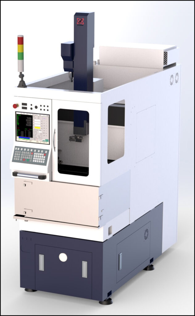
Features
Compact Footprint
Maximizes floor space with its compact footprint, which allows for close proximity of multiple machine setups
6 Coordinate Systems
Allows up to 6 jobs to be run consecutively in a single setup
3 Step Control of EDM Parameters
Program up to three EDM parameter settings per hole to improve hole quality on difficult entrance and exits
Automatic Electrode Stabilizer
Moves automatically to provide extra support for long electrodes
1000 RPM Programmable Spindle
Rotation speed is adjustable and will reduce cycle time for some applications
Windows Based
With conversational G and M Code programming
Multi-Tasking Abilities
Create and edit one program while the machine is running another
Ethernet Connectivity and USB Support
For programming and transferring of data
Automatic Depth Control
Generate blind holes reliably without operator intervention
Linear Glass Scales with 1 Micron Resolution
Provides true, closed loop, position feedback for precise part positioning accuracy
Auxiliary I/O
Ability to interface with ancillary devices such as rotary tables, indexers, and work piece handling systems
Automatic Electrode Changer
Allows for a large volume of unattended operation
Automatic Guide Changer (Optional)
Allows for a large volume of unattended operation
Integrated Rotary and Tilt/Rotary Tables (optional)
Programmable tilt and rotary systems for complex parts requiring multi axis positioning
Break Through Detection (optional)
Ensures a complete hole or helps to eliminate back wall strikes
Optical Inspection System (optional)
High resolution video camera can measure hole size, verify position, and locate datum points for part programs
EDM Power Booster (optional)
Increases the maximum average current which will reduce the cycle time when using larger diameter electrodes
EDM Milling (optional)
EDM mill shaped diffuser holes using standard cylindrical electrodes
6 Point Probing (optional)
Probe the work piece to determine its 5 axis location and offset position in the part program
Coaxial Flush (optional)
A special guide and guide sleeve delivers auxiliary flush down the guide body
Programmable High Pressure Flush (optional)
Adjust the high pressure flush pressure through the electrode with a G-Code in the part program
Specifications
| TRAVEL | X Axis | 11.8” | (300 mm) |
| Y Axis | 11.8” | (300 mm) | |
| W Axis | 20.4” | (520 mm) | |
| Z Axis | 19.6” | (500 mm) | |
| OPEN HEIGHT * | Minimum | 1.5” | (40 mm) |
| Maximum | 22.0” | (560 mm) | |
| WORK TABLE | Width | 22.0” | (560 mm) |
| Depth | 17.5” | (445 mm) | |
| INTERNAL WORK TANK DIMENSIONS | Width | 24.0” | (610 mm) |
| Depth | 22.6” | (575 mm) | |
| Height ** | 13.0” | (330 mm) | |
| Maximum Water Level ** | 11.8” | (300 mm) | |
| WEIGHT CAPACITY | On Work Table | 770 lb. | (350 kg.) |
| GENERATOR | Maximum Average Current | 30 A | |
| On and Off Time | 1 to 99 µs | ||
| Capacitors | 0 to 1.81 µF | ||
| AUTOMATIC ELCTRODE AND GUIDE CHANGER | |||
| AEC Positions | 12 | ||
| AGC Positions | 12 | ||
| FLOOR SPACE AND WEIGHT |
Width | 32” | (81 cm) |
| Depth | 79” | (201 cm) | |
| Height | 98” | (249 cm) | |
| Weight | 3,230 lb. | (1,465 kg.) | |
| ENVIRONMENTAL | Room Temperature | 68 to 77˚F | (20 to 25˚C) |
| Relative Humidity | 40% to 55% | ||
| UTILITIES | Electrical | 220VAC ±10%, 3 PHASE, 60 Hz, 3.5 KVA | |
| Air | 90 PSI @ 1 CFM | (6 BAR @ 1.7 CMH) | |
* Open Height is measured from tip of a standard ceramic guide.
** Work tank height and maximum water level is measured from the top of the work table.

